
VOLEȚI CU SERVOMOTOR SD-EI120S-M
The smoke control dampers are used in ventilation and air conditioning installations from office buildings, industrial buildings, commercial spaces, hospitals, auditoriums andcompetition halls.
The dampers for the control of smoke and hot gases are used in smoke and hot gas control systems as measures of venting smoke and for lowering the number of fire-resistant pipes and fans.
The system for smoke and hot gas control can evacuate the smoke either by using fire resistant fans or by natural ventilation.
The pipes on which smoke control dampers are mounted generally serve several fire compartments. The systems can be used exclusively for smoke evacuation or can be part of a mixed system of ventilation/exhaust.
The dampers open at the request of the fire prevention installation, with the help of an electromagnet. These must fulfill the following conditions: smoke and hot gas tightness, mechanical stability and maintain their cross-section.
Depending on the scenario for fire and placing, the SD-EI120S-M acts so:
- remain closed, in which case it insulates the respective compartment from the hot gases that are exhausted through the column on which the damper is mounted;
- open at the occurrence of the event in order to allow the suction of smoke and hot gases from the enclosure;
open at the appearance of the smoke for its atmospheric evacuation and for fresh air intake.
Our company produces rectangular smoke control dampers for the control of smoke and hot gases which are tested according to follow documents:
- Fire resistance tests of smoke control dampers according to European standard EN 1366-10+A1;
- Fire damper tested at PAVUS Fire Testing Laboratory;
- Fire resistance tests – Part 1: General requirement according to European standard EN 1363-1;
- Aerodynamic testing of dampers and valves according to European standard EN 1751;
- Classified product as fire resistant element in buildings according to European standard EN 13501-4
- Smoke extraction tests according to European standard EN 1366-8
Smoke and heat control system of smoke control dampers which are tested according to European standard EN 12101-8.
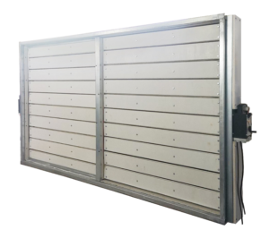
DESCRIPTION OF THE CONSTRUCTION
The damper for smoke control is made of opposable blades made of class A fireproof material with a 40 mm thickness, environmentally friendly building material, the magnesium oxide plate is strong and resistant thanks to the very strong connections between the magnesium atoms and oxygen which form magnesium oxide crystals (with the chemical formula MgO).

The blades are mounted in a housing made of the same material, with a thickness of 20 mm. Case is provided on both sides with metal flanges for connecting to ducts ventilation.
The case is made from MGO board of 20 mm. Case is provided on both sides with metal flanges (thickness – 1.2mm) for connecting to ducts ventilation. Fixing the flange to case is done with pop rivet 5x30mm.
The locking elements (opposable blades) are made of MGO boards, with 40 mm thickness ( 2 layers of 20 mm), Fixing between boards is made with M5x45 bolts and joint paste NevPanel. This thickness ensures fire resistance for 120 minutes.
The forces to which the door can be subjected being able to reach up to 100 Kg/m2. The blades have at their ends Ø 10 steel shafts through which it is the performed the mechanism turning. The shafts pass through bushing in the case.
Between the housing and the blades there is inox profile of 0.4 mm. Attach to this there is intumex gasket( 30 x 1.8 mm) that expands at high temperature and EPDM silicone rubber gasket, type „D” for ensuring leakeage at ambient temperature. These components ensures sealing if the blades must remain close.
On blades for providing insulation at high temperatures, intumescent gasket (10 x 1.8 mm) is applied through out the entire length of the blade. For cold insulation it is applied EPDM silicone rubber gasket, type „D”, on the length of the blade.
 The atuation mechanism is made of multiple components of different thickness (1.5 – 2 – 3 mm), mounted at the end of the shafts. These parts are laser cut for high accuracy. These components are fixing with screws for adjustments of the blades. After adjustment is complete components are welded toghether.
Over the actuation mechanims is mounted a galvanized metal case of 1mm and MGO board of 20mm for protection. On this case is also mounted the actuation motor. To fix the motor use M5x80 mm bolts and rivet nut M5.
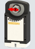
The SD-EI120S-M are equipped with Gruner type actuator, mounted on the shaft of the locking blade. When the actuator is supplied with voltage, it rotates by bringing the damper to the closed/open position.
The smoke control dampers with actuators close or open depending on the purpose for which they have been mounted in the ventilation system.
Triggering and control mechanisms: axial actuator, within the series of products intended for smoke control dampers.
The proper functioning of the SD-EI120S-M is ensured when the axis of rotation is the horizontal one.
The assembly of the smoke control dampers in the piping is carried out by connecting them with the angle brackets / vises. Following a proper mounting of the smoke control damper, in case it has controls or other elements that require connection to the electrical system, the cables of this system must resist to fire 100 seconds and must be properly connected to the smoke control damper.
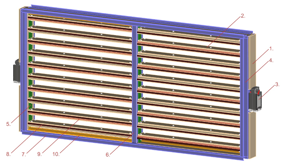
- Smoke damper case – MGO – 20mm
- Smoke damper blades – MGO – 40mm
- Actuator – Gruner servomotor
- Actuator support – galvanized steel – 1mm
- Inox profile – SS304 – 0.4mm
- Profile “U” – galvanized steel – 1mm
- Flange – galvanized steel – 1.2mm
- Intumescent band – 5×1.8 mm
- EPDM silicon rubber gasket – type “D”
- Blade stopper – profil “L” – galvanized steel – 1mm
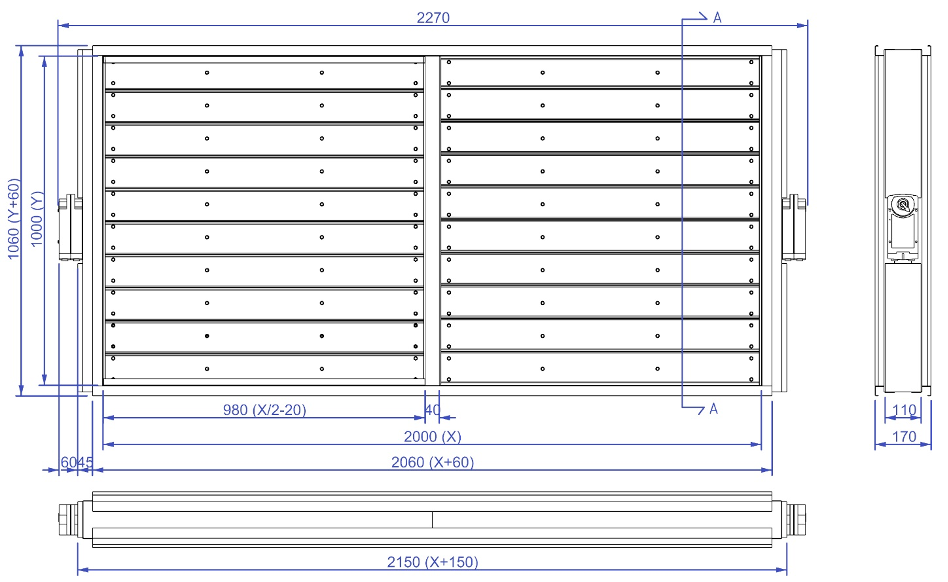
INTERIOR AND EXTERIOR SIZE
To know the exterior size of the SD-EI120S-M, on the Y axis, calculate the inner dimension + 60 mm, representing the outer flange. On X axis, in addition to the 60 mm are added 105 mm (for single compartment) or 210 mm for multicompartiment representing the motor and support for it.
The depth of SD-EI120S-M is 170 mm.
The free surface is 60% of effective area – X x Y x 0,6.
Usual dimensions – horizontal(X); vertical (Y) – according to the table:

Upon the customer’s request, there can be made atypical dimensions or 2-door dampers where normally a single door is used to block the fire.
TECHNICAL SPECIFICATIONS
DECLARATION OF PERFORMANCE
| The unique code of the product | SD-EI120S-M |
|---|---|
| Purpose | The smoke damper are used in ventilation and air conditioning installations in 3 states:
They open to evacuate the smoke from the room. |
| Manufacturer | SBI Steel Industry SRL, Aurel Vlaicu street, no.13, Ilfov, Romania |
| Declaration of Performance according to EN 12101-8 standard | Fire resistance according to EN 1366-10 and classifications according to EN 13501-4 |
CERTIFICATION
The tests were performed according to the European standard(EN) 1366-10+A1;
Classification according EN 13501-4;
Smoke and heat control system according to EN 12101-8;
Aerodynamic tests of the damper and the door in accordance with EN 1751;
CE mark.
CLASSIFICATION
The SD-EI120S-M have the following classification:
EI 120 (Ve i <-> o) S1000 C300 AAmulti
Where the symbols represents:
- E – smoke resistant
- I – fire protection
- 120 – resistance to smoke and hot gases for 120 minutes
- Ve – smoke damper is closing vertically
- I <-> o – sense of protection insurance: interior -> exterior and exterior <- interior
- S1000 – smoke tightness, tested at 1000 Pa
- C300 – the number of cycles at which the product was tested
- AA – automated control multi – multichamber
CODING

ESSENTIAL FEATURES
- The dampers are made of fireproof material class A and consist of one or two doors, the frame being made of the same material, metal flanges for assembly.
- Air flow – until 26920 m3/h at 12 m/s
- Air leakages through the C-class housing according to EN 1751
- Air leakages with Class 4 closed blade according to EN 1751
- Rezistență la coroziune în conformitate cu EN 15650
- The permeability degree is according to IPX 4
- As concerns the danger of electric shock, the products belong to the following categories of electrical appliances:
- Class III (low voltage) for shock absorbers with 24 V power supply;
- The smoke dampers may not be mounted in enclosures or air channels with the danger of explosion, air pipes for flammable or explosive mixtures.
- The dampers are intended for use in non-aggressive environments, with an air temperature between -20 ° C and + 60 ° C and a relative humidity of up to 80%.
OPERATING TYPE FOR SMOKE DAMPER
To operate the opening and closing of smoke damper blades our company equips the product with special actuator for smoke control.
Depending on the size of the damper, it can be chosen the power of the actuator. The fire-resistant fire dampers are equipped with servomotor made by Gruner – Germany.


Coresponding between motor power (Nweton x meter) and servomotor type is:
- 15NM power – servomotor 342 S2 type
- 40NM power – servomotor 362 S2 type
After choosing the motor power, it will be opted for the operating voltage. This can be 220 or 24 volts.
DELIVERY AND ACCOMPANYING DOCUMENTS
DELIVERY
The delivery of smoke control dampers will only take place accompanied by the following documents:
- Document of origin
- Certificate of conformity issued by the manufacturer
- Declaration of performance according to the Construction Products Regulation
- Directions for installation
- Maintenance and operating directions
On the fire damper it is attached the product label specifying the product identification data (sizes, batch series, manufacturing date), as well as the CE marking number.
Delivery will be made individually or grouped on the pallet, depending on the number and the volume occupied by the smoke dampers.
The beneficiary has to check the compliance of these data with those of the ordered product.
POST-DELIVERY WARRANTY
The warranty period of the product is 24 months from the date of signing without objection the document of origin (delivery note and/or invoice), but not more than 65 months from the delivery, subject to putting into operation according to the technical documentation and compliance with the conditions of transport, handling, storage and assembly according to the directions, as well as to carrying out periodic maintenance of a period of maximum 6 months.
- Handling of the product will be done manually, while complying with the labor protection norms regarding the weight and the protection equipment required for handling.
- The transport will be carried out in such a manner that during the loading/unloading and travelling it is not allowed to strike, bend or destroy the product.
- The product storage will be made in specially arranged places until the date of assembly. The storage area will be protected from the action of atmospheric agents.
- The assembly, operation and periodic verifications of the product/spare part will only be executed by qualified or authorized personnel.
- During the warranty period, there will be borne all costs incurred withfixing theproduct broken-down due to hidden material defects or manufacturing defectsthat can be proven.
- Notification of the producer by the beneficiary concerning the defect of the product within the guarantee time limit will be in writing (letter or fax) or by e-mail with the highlighting of the defect type as detailed as possible.
- It can be also provided guarantee against a fee for the repaired products or spare parts which are outside the warranty period.
Speciale mentions:
The guarantee right will be lost if the beneficiary:
- Damages the product during transport or due to improper handling;
- Damages the product due to thermal, mechanical or plastic actions caused by fire, mechanical tensions, weathering or assembly not in compliance with the manufacturer’sinstructions or the norms and laws in force, applicable in the field of construction;
- Operates the product in humid, corrosive environments, excess dust, limit temperatures, other than those for which it was designed;
- The product is operated by other persons than the trained/qualified or authorized personnel;
- The beneficiary is advised that, for the proper functioning of the product, to ensure the execution of regular maintenance operations, respectively checking the integrity and functionality of the components.
STORAGE AND TRANSPORT
TRANSPORT
For transport the smoke dampers, will be individually packed or grouped on a wooden pallet and wrapped. In the truck it will be ensured a protection against shocks. It is not advisable to transport in uncovered cars if the weather is unfavorable.
During transport, the dampers for smoke control must be in the closed position.
Check the smoke dampers at the goods arrival to see if there is any damage. In case it is found any damage or lack, please contact immediately the shipping company and the supplier.
STORAGE
For the storage of the damper a longer time please have in view the following:
- Protect the damper from exposure to dust or other contaminating materials;
- Do not leave it exposed to the action of the weather;
- Keep the damper packed as much as possible, if possible, until the assembly;
- Storage temperature -30 / 60 degrees C.
MOUNTING ISTRUCTIONS
MOUNTING
Before starting the mounting properly, please read these directions for installation.
The assembly should be carried out by qualified personnel, such as electricians, HVAC technicians, or persons with technical knowledge.
Before mounting, the damper will be checked visually if during transport and storage it has or not not been damaged or if there are no materials or debris inside it that could affect the damper functioning.
It will be checked manually if the closing system is functioning properly.
Before mounting it will be checked that the two dimensions of the air passage section, the width and the height of the damper be identical to that of the piping where it will be mounted.
The dampers are mounted on the ventilation ducts and / or at the passaing through the walls that define the fire compartments.
Depending on needs, mounting holes and openings in walls will be made accoring to it.
Before installation, each damper is inspected visually and checking that the door / doors open without any friction.
The smoke damper is fixed to the duct through the metal flange.
Following the installation, check that damper is functioning properly.
The smoke damper can be mounted on the ventilation duct as the end of it.

- Ventilation Duct
- Gasket
- SD-EI120S-M
The damper is mounted on the ventilation duct by means of screws, M8 nuts and screw clamps (vises), after mounting to the connection flange the high temperature resistant sealing tape or high resistant silicone. After installation, a layer of RF mineral wool 120 minutes will be applied on the body of the smoke.
On the side of the ventilation duct.

- Duct ventilation
- Gasket
- SD-EI120S-M
The mounting is performed similar to the first position of the damper, the difference being the position on the duct ventilation.
MAINTENANCE
In order to ensure the correct and uninterrupted operation, the SD-EI120S-M dampers must be inspected and operated regularly.
Rectangular smoke control dampers require an execution of service verifications every six months. Each check of the rectangular smoke control dampers shall be ended with an appropriate protocol.
Rectangular smoke control dampers are an integral part of an installation. It is recommended to check the system assembly according to the requirements for operating and maintenance corresponding to the installation.
The lifetime of SD-EI120-M rectangular smoke control dampers is 25 years.
Controls recommended for smoke control dampers
| Operation / task | Result |
|---|---|
| Fire damper reference | |
| Control date | |
| Checking the damages related to the wiring of the actuating mechanism (if appropriate) | |
| Checking for damages related to the end switch wiring (if applicable) | |
| Checking the fire damper cleanliness and cleaning if necessary. | |
| Checking the condition of the blades and seals, correcting and recording if necessary. | |
| Confirming the functioning of the safety closing of the fire damper according to the manufacturer’s instructions. | |
| Confirming the opening and closing of the fire damper with the help of the control system and by visual observation of the fire damper, correcting and recording if necessary. | |
| Confirming the opening and closing of the end switches, correcting and recording(if applicable). | |
| Confirming whether the fire damper fulfills its role within the control system (if applicable). | |
| Confirming if the fire damper is in the normal operating position |